TyNoise Suppression Products/EMI Suppression Filters
Reasons for requiring EMI suppression filters (EMIFIL ® )
1-1. Introduction
An EMI suppression filter (EMIFIL ® ) is an electronic component for providing electromagnetic noise suppression for electronic devices and is used in conjunction with shields and other protection. This filter only extracts and removes components that can cause electromagnetic noise from electric currents that are conducted through wiring. Chapter 1 describes the reasons for using EMI suppression filters (EMIFIL ® ) in electronic devices and also provides an overview of the operations of shields and filters that are typical parts used for electromagnetic noise suppression.

1-2. What is electromagnetic noise interference?
When electronic devices receive strong electromagnetic waves, unwanted electric currents can be induced in the circuit and thus cause unintended operations or interference with the intended operations. If the energy applied from the outside is too powerful, electronic devices can be damaged. Even if the energy applied from the outside is small, if it is mixed with the radio waves used for broadcasting and communication, it can cause loss of reception, abnormal noise in sound, or disrupted video at places where the radio waves for broadcasting and communication are weak. Such interference caused by external electromagnetic waves is called electromagnetic noise interference, and the electromagnetic waves that cause interference are called electromagnetic noise (hereinafter, noise).
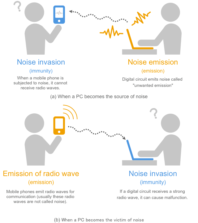
Fig. 1-2 Emission and immunity
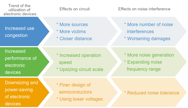
Noise can cause interference with various electronic devices. The source of noise also varies. Noise that does not cause any interference with particular appliances (e.g. washing machines and refrigerators) can seriously affect other devices (e.g. AM radios). Therefore, there are rules to suppress the noise generated from electronic devices to a certain level and to make sure that electronic devices operate correctly under a certain noise level so that we can use electronic devices with security. These rules are called noise regulations.
If an electronic device is considered a source of noise, the occurrence of noise is called emission (emission of noise). In contrast, if an electronic device is considered a victim of noise, the tolerance to noise is called immunity (noise tolerance). Noise regulations specify the emission and immunity of electronic devices. (Immunity is also referred to as EMS: ElectroMagnetic Susceptibility)
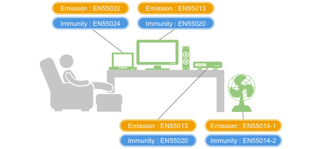
1-2-1. Classification of electromagnetic noise
Electromagnetic noises can be classified into natural noises and artificial noises based on the source origin of electromagnetic noise as shown in the figure.
Natural noises are those that existed before the existence of electronic devices, for example, lightning and static electricity. Electronic devices are required to have immunity to natural noises. Artificial noises are noises that came to be after electronic devices started to be used and are dealt with both emission and immunity. As electronic devices have become more commonly used, the interference caused by artificial noise has increased. This point will be described in detail in the next section.
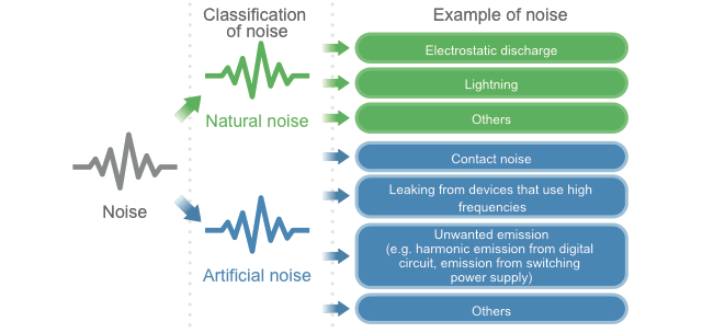
1-2-2. Change in noise issues due to congestion of electronic devices
The congestion of electronic devices used around our vicinity is increasing, and the content and degree of noise interference are changing as the performance of each electronic device increases. For example, before 1970 (before digital circuits became popular), we were concerned about issues of interference (radio interference) between wireless radios. However, as household digital devices such as personal computers became popular, we became more concerned about receiving interference to the reception of radio and TV by the radio waves generated by those devices.
In general, as the congestion of electronic devices increases, the distance between source and victim is reduced, resulting in an increasing degree of noise interference. In addition, as the performance of electronic devices increases, the operating circuit frequency increases and noises of higher frequencies are generated, resulting in an expanding affected frequency range. Furthermore, due to the power saving capability of electronic devices, more circuits can operate with a lower voltage, resulting in more cases of being affected by noise with less energy.
With the further increase in congestion and performance and the downsizing of electrical devices, the issue of noise interference is expected to become more serious.
1-2-3. “Intra-system EMC”, the autointoxication of an electronic device
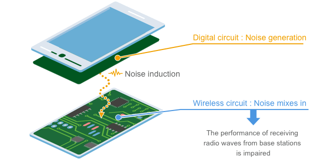
Noise interference can occur to electronic devices without any external noise. Noise generated from a circuit inside an electronic device can cause interference with another circuit in the same electronic device. This is called intra-system EMC. For example, if a mobile phone has a built-in digital circuit, noise from the digital circuit can degrade the receiver performance of the mobile phone (reducing the receiver sensitivity) as shown in the figure below. In such a case, the distance between the noise source origin and the victim is significantly smaller than those of general noise interferences, causing more serious interference. Depending on the case, noise suppression is provided on a level far stricter than the limit of noise regulations.
1-3. Noise suppression
Noise interference occurs when three factors (noise source, victim and transmission path) exist as indicated by the principle diagram in Fig. 1-7. Noise interference can be eliminated if you can eliminate one of these factors.
Therefore, you can take measures on the noise source origin side or on the victim side. For example, if you do not use digital circuits, switching power supplies or transmitters (e.g. incandescent lamps), the noise generated from the electronic devices will be very small. Another example would be setting up redundancy processing in software on the victim side.
So, even if the information is slightly altered, the signal can be recovered. These measures can be fundamental solutions. But, many such cases can cause large secondary effects like significantly reducing the performance of electronic devices or increasing their size, making such measures unrealistic.
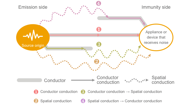
Fig. 1-7 Principle of noise interference
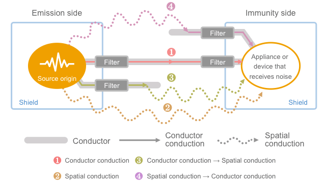
Usually, noise is shut out in the transmission path as shown in Fig. 1-8. There are two types of noise conduction (spatial conduction and conductor conduction). As shown in the figure, the spatial conduction is dealt with by shields, while the conductor conduction is dealt with by filters.
As shown in Fig. 1-7, spatial conduction and conductor conduction have a tendency of mutual transformation through a wire that works as an antenna. Therefore, even if conductor conduction is only a problem at one location, you cannot completely ignore the possibility of spatial conduction.
1-3-1. Shields
Shields refer to surrounding electromagnetic fields being shut out by enclosing the target object with a metal plate or other protection as shown in Fig. 1-9.
Although the effects of shields generally depend on the conductivity, magnetic permeability and thickness of the material used, the noise suppression for general electronic devices can achieve sufficiently large effects with a very thin metal plate such as aluminum foil. You must be aware that the effects of the noise suppression for electronic devices often depend on the connection method for forming an enclosure (gaps, contact resistance etc.) rather than the material specifications.
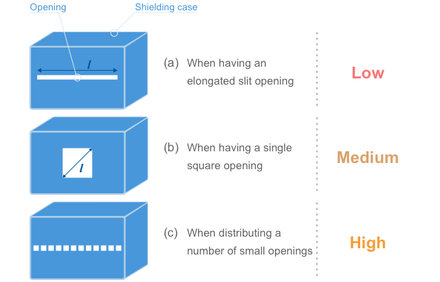
When making openings in the shield for heat release, limiting the maximum size of each opening is more important than limiting the total area of the openings. As shown in Fig. 1-10, if there is an elongated opening or slit, this part can work as a slit antenna (especially for high-frequency range where the length l in the figure exceeds 1/2 of the wave-length) and the radio waves can go in and out the shield. In order to prevent this, the individual openings should be kept small. From this viewpoint, plate materials with many small holes such as punched metal and expanded metal are good materials for both ventilation and shielding.
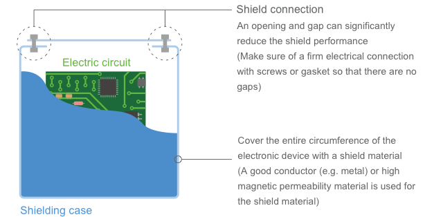
Fig. 1-9 Shield
(It is assumed that high frequency noise is confined by the electromagnetic shield.
In some cases (e.g. electromagnetic shield etc.), this order may not be applicable)
1-3-2. Filters
Filters refer to a part or function that can let the necessary components through and remove unwanted components among the electric current flowing in conductors. Although the noise is diverted to ground in Fig. 1-12, the noise energy can be alternatively absorbed inside the parts or can be returned to the noise source origin (increasing the impedance).
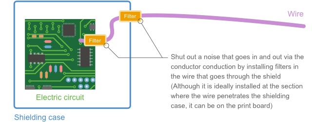
Fig. 1-11 Filter

Fig. 1-12 How a filter works
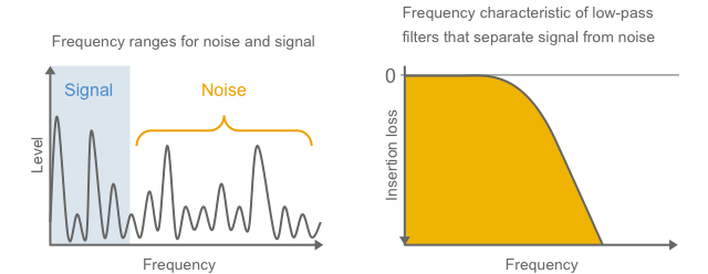
Since noise tends to be distributed more in a relatively higher frequency range as shown in Fig. 1-13, the noise suppression for electronic devices usually uses low-pass filters that remove high-frequency components. You can use general-purpose parts such as inductors (coils), resistors and capacitors for this low-pass filter. However in order to completely shut out noise, a dedicated component, an EMI suppression filter, is used. EMI suppression filters will be described in detail in Chapter 3 of this document.
Apart from these filters that take advantage of uneven frequency distribution of noise, there are filters that take advantage of the voltage difference (varistors etc.) and filters that take advantage of the conduction mode difference (common mode choke coils etc.).
In addition to these filters, transformers, optical cables or optical isolators may be used as a kind of filter. Although these components can achieve exceptional denoising effects in some cases, the applicable situations are limited.
1-4. How to use shields and filters
1-4-1. Use shields and filters at one point
Filters are used for noise that conducts through conductors, while shields are used for noise that conducts through space. However, since the conductor through which noise conducts can also work as an antenna, these two types of conductions are mutually transformed into each other via the conductor as an antenna. Therefore, in order to completely shut out noise, both filters and shields need to be used at one location.
For example, when a shield is used for shutting out spatial conduction, if there is a conductor that penetrates through the shield as shown in Fig. 1-14, this conductor picks up and draws the noise inside the shield to the outside of the shield causing noise emission. As a result, spatial conduction cannot be completely shut out solely with a shield.
Likewise, when a filter is used for shutting out conductor conduction, the wires before and after the filter may be coupled with each other via spatial conduction as shown in Fig. 1-15. As a result, the conductor conduction cannot be completely shut out solely with a filter.
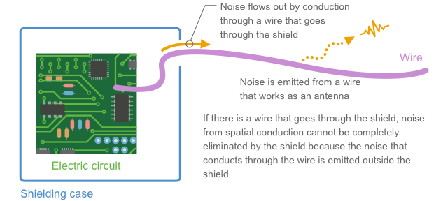
Fig. 1-14 Conductor conduction causes loophole in a shield
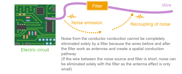
Fig. 1-15 Filter is bypassed by spatial conduction
When using both a shield and filter together at one location as shown in Fig. 1-16, both spatial conduction and conductor conduction are completely shut out allowing complete noise elimination.
If the length of the conductor between the noise source and filter is significantly short as shown in Fig. 1-17, the effect of the conductor as an antenna can be ignored and the noise can be thus eliminated only with a filter to a certain extent. Therefore, if you can use a filter at a close vicinity to the noise source, the noise suppression can be achieved only with a filter.
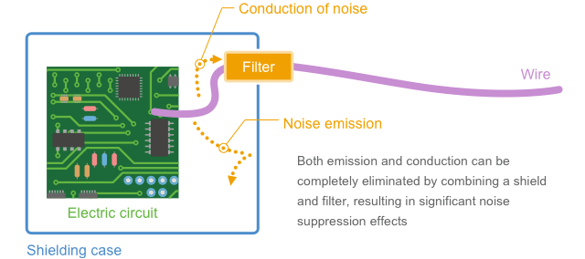
Fig. 1-16 Noise can be shut out by the combination of a filter and shield
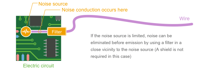
Fig. 1-17 If conductor is short, noise suppression can be achieved only with a filter
1-4-2. Filters and ground
In order to effectively use filters and shields, it is generally necessary to have a connection with good ground.
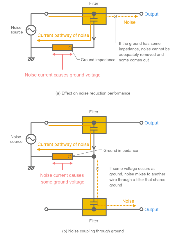
If there is a built-in bypass capacitor inside the filter, ground becomes a route to return the noise current back to the noise source as shown in Fig. 1-18. You need to consider keeping the impedance of this part very low.
If the impedance to ground is large as shown in Fig. 1-19(a), some voltage appears at ground due to the noise current interfering with good noise elimination. If this ground is shared with another wire attached to another filter, the voltage appeared at ground can go back to other wires through the filter capacitor.
This type of noise coupling through the impedance of ground is called common impedance coupling. This status of having noise on ground is also referred to as the occurrence of common mode noise. Common mode noise will be described in a later chapter. The common impedance coupling is one of the mechanisms that cause common mode noise.
Since the effect of filters that have built-in capacitors are highly susceptible to the conditions of the connected ground, you need to use a stable ground with a low impedance.
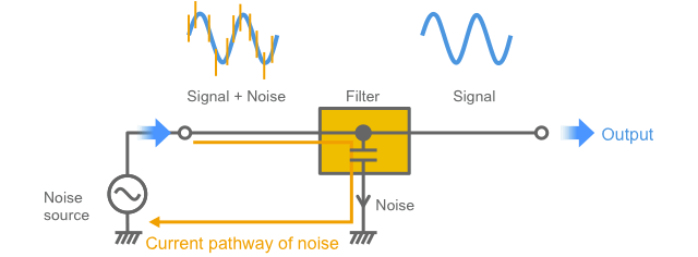
Fig. 1-18 Current pathway of noise
1-4-3. Shields and ground
Shield also need ground.
Static shields must be connected to ground that is in principle an external earth (zero volts). Since an electrical current flows on the wire connected to ground in accordance with the change in the electric field to be shielded, the wire needs to have a low impedance.
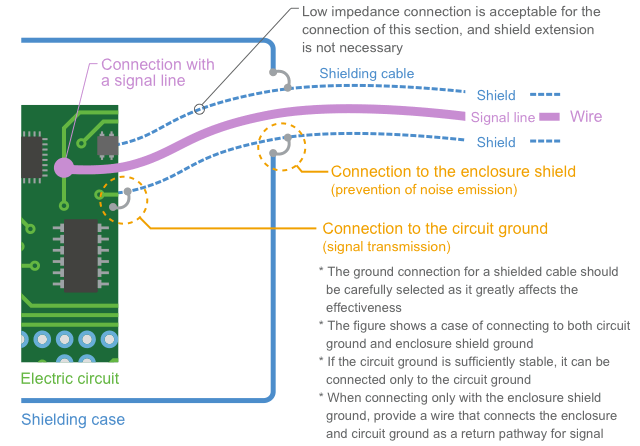
In many cases, when using shielded cables, the shield also works as a return pathway for the current that has gone through the inner conductor (such as the outer conductor of coaxial cable for example). Therefore it needs to be connected to ground that can return this current (when shielding a signal, connect to the circuit ground).
In cases where the noise has been guided to ground as is the case of Fig. 1-19, if shields are connected to this ground, the shield draws out and then emits the noise from ground working just like as an antenna, which could increase the noise. When connecting shields, you need to choose a low impedance ground with a stable potential.
Enclosure shielding cases practically work as a relatively good ground. If there is a shielding case that covers the entire device, this shielding case itself can be a good ground for the purpose of noise suppression even though it is not connected to earth (if the discharge current needs to be drained to earth for the purpose of suppressing static electricity or other currents, it needs to be connected to earth). Here, we call this ground an enclosure shield ground.
This enclosure shield ground can also be used as ground for the shielded cables. However, in order to make this shield work as a return pathway for signals as described above, it also needs to be connected with the circuit ground. Therefore, if the enclosure shield ground and the circuit ground have been separated, the connection gets complicated.
1-4-4. Reinforcement of ground
As described above, connecting to a stable ground is necessary for enhancing the effect of filters and shields. In addition, when using a shielding case that covers the entire device, this shielding case itself can be used as a stable ground. Therefore, shields generally have a function to stabilize ground.
If there is a wire that goes through this shielding case, you are providing a hole that allows noise going in and out of the shield as shown in Fig. 1-14 making the shielding case ground unstable. In such a case, you can use filters in this wire to stop noise from going in and out so that the shielding case ground can be stabilized.
Since appropriately applied shields and filters will work for stabilizing ground as described above, there is a mutually helpful relationship between shields, filters and ground.
Circuit ground is also a type of ground apart from the above-described shielding case ground and often induces more noise voltage than the shielding case ground does. This kind of ground is called “dirty ground.” In contrast, a ground where noises are not induced is called “clean ground.”
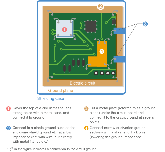
It is desirable that ground to which shields or filters are connected is a clean ground. However, a circuit ground connection is required to return the signal return current or to return the noise current back to the noise source origin. If the circuit ground is dirty, the noise voltage should be minimized by reducing the impedance of the circuit ground, providing a ground plane along the circuit board, or connecting with the enclosure shield ground.
The operation of stabilizing the ground noise by reducing the voltage in this manner is referred to as “ground reinforcement.” Covering a part of the circuit board with a shielding case helps the ground reinforcement. Fig. 1-21 shows some of the methods for ground reinforcement.
1-4-5. Filters and ground
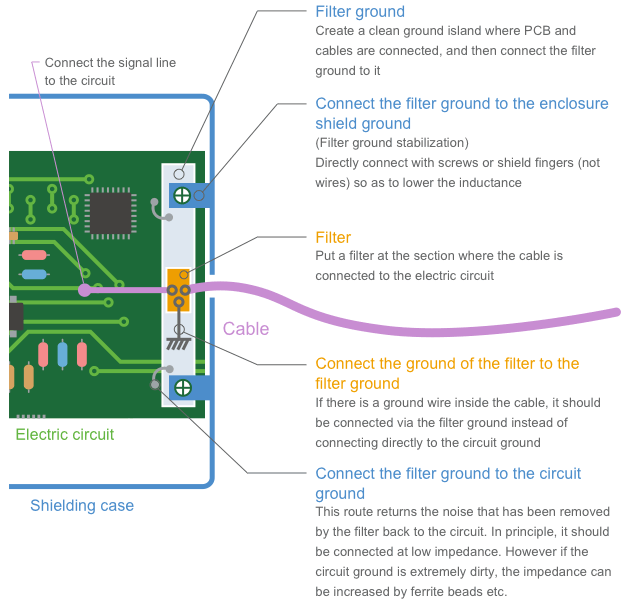
When connecting cables to the shielding case, filters are attached to prevent noise from going in and out through the cables. Ground of this filter is to be formed on the circuit board. However, in order to stabilize ground, it is often connected to the shielding case ground instead of the circuit ground. Therefore, ground for filters that are connected to the shielding case ground is often created at the section where the cables are attached. Here, we call this ground a “filter ground.”
In general, a filter ground is not only connected to a shielding case ground but also connected to a circuit ground in order to return the noise generated inside the circuit to the noise source. In this case, it also works for ground reinforcement for the circuit ground at the same time. When using shielded cables, the shield can be connected to the filter ground. In this case, it must be connected to the shielding case ground at a very low impedance as the effectiveness of shielded cables depend on the quality of the filter ground.
Fig. 1-22 shows an example of a filter ground. It is important to keep the filter ground at a very low impedance with reference to the shielding case ground.
Although Section 1-4-2 has explained that ground of the filter is to be connected to the noise source at a low impedance (with reference to the circuit ground), Fig. 1-22 shows that the connection to the shielding case ground is given a priority. This is because it is practically difficult to return to the noise source at a low impedance as the connection point of cables are usually far from the noise source. It is also because it is hard to get a good result by connecting the filter ground at a low impedance as the circuit ground is often dirty due to noise from other circuits.
Therefore, when using a filter for a single circuit at a close vicinity to the noise source, the filter is connected to the circuit ground as explained in Section 1-4-2. However, this connection is not easily achieved when the noise source is far away (such as a case of cable junction) and two or more noise sources need to be considered. As a practical technique, when using filters at a cable junction, you can find a stable ground such as a shielding case ground as shown in Fig. 1-22 and connect the filter ground.
 Chapter 1 – Key points
- An electromagnetic wave that interferes with the operation of electronic devices is called noise.
- The means to shut out the noise in the transmission path include shields and filters.
- In order to make shields and filters work effectively, grounding is important.
Mechanism of Causing Electromagnetic Noise
2-1. Introduction
Chapter 1 described the mechanism of causing interference by electromagnetic noise and the overview of noise suppression. Noise suppression is mainly implemented in the noise transmission path with use of shields and filters as the typical means. In order to use these means efficiently, it is important to have a deep understanding of the mechanism of the occurrence and propagation of electromagnetic noise.
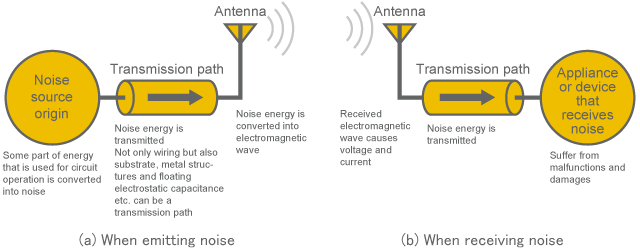
With close reference to the principle of noise occurrence described in Chapter 1 in terms of noise source, there are three factors: noise source origin, transmission path and antenna (assuming that the noise interference is eventually propagated in the form of electromagnetic waves, antenna is included here) [Reference 1] as shown in Fig. 2-1-1(a). In case of becoming a noise victim, exactly the same schematic diagram can be used as shown in Fig. 2-1-1(b) by flipping the drawing horizontally and replacing the noise source origin with a noise receiver. That means the mechanism can be considered as the same in both cases of generating and receiving noise.
Therefore, in order to have a deep understanding of the mechanism of noise interference, Chapters 2 to 5 focus on the issues regarding the noise source side and describe the basic theory of the mechanisms of causing, transmitting and emitting noise. In these chapters, shields for shutting out noise and ground connections are also briefly described. Another important factor “filter” will be described in detail in a later chapter.
First of all, Chapter 2 will describe the mechanism of causing noise.
2-2. Noise source origin
There are various situations to cause an electric current that can be a noise source. For example, a certain signal component is needed for the operation of one circuit while causing a problem for other circuits. In another case, noise may be inevitably generated despite that none of the circuits want it. Sometime the noise may be caused rather as a result of carelessness. Of course, the mind-set towards the noise suppression varies depending on each situation. However, it is easier to handle the situation if you can understand how the particular noise has been caused.
In this chapter, we will take the following three typical cases of noise sources to understand the mechanism of causing noise and the general coping strategies.
- (i)Signal
- (ii)Power supply
- (iii)Surge
2-2-1. In case that signal becomes a noise source or victim
In this section we call the lines that primarily transmit information as signal lines. Generally in order to transmit information through an electric circuit, some amount of electric current is required even if it is very small. Then, the current creates an electromagnetic field around it. When the current changes in accordance with the information, it emits radio waves to the surrounding, which in turn is causing noise.
As the amount of information increases, the frequency of the electric current that goes through the signal line increases, or more lines may be required. Generally the higher the current becomes, or the higher the number of lines becomes, the stronger the radio wave is likely to be emitted. Therefore, the higher the performance of electronic devices becomes, and the more information is handled, the more likely that the signal lines used in the electronic devices can easily cause noise interference.
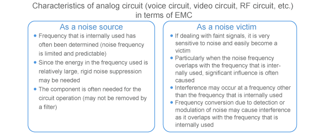
Electrical circuits that transmit information can be broadly classified into analog circuit and digital circuit, wherein analog signal and digital signal are respectively used. The general characteristics of those are described below from the viewpoint of circuit noise.

Fig. 2-2-1 Analog signal and digital signal
(1) Analog circuit
From the viewpoint of noise source origin, analog circuits tend to generate relatively less noise since those only use limited frequencies and are designed to control the flow of electric current.
But still, if some of the energy leaks to the outside, it can be a cause of noise interference. For example, receivers for TV or radio use a signal with a constant frequency called local oscillator frequency in order to selectively amplify the targeted frequency from the radio waves that have been received by the antenna. If this leaks to the outside, it can cause interference to other devices. In order to prevent this from happening, the tuner section is shielded or EMI suppression filter are used for the wiring.
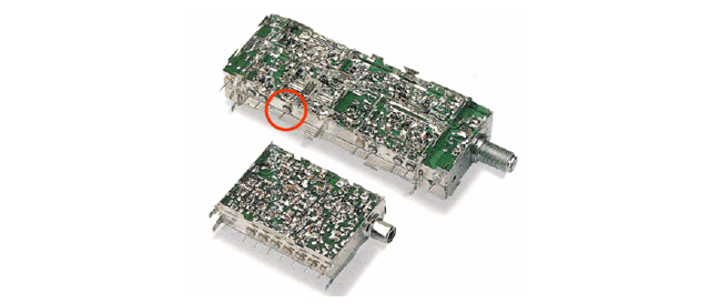
Fig. 2-2-2 Example of electronic tuner in which EMI suppression filters (feed-through capacitor) are used
In contrast, from the viewpoint of noise victim, since analog circuits often deal with faint signals and the information is affected by even small fluctuations, the circuit tends to easily become a noise victim. For example, if noise enters to the first stage of a voice amplifier, the speaker will make a loud noise sound by detecting and amplifying it. In order to prevent this from happening, highly sensitive voice amplifiers are shielded or EMI suppression filters are used for the wiring.
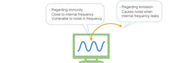
Fig. 2-2-3 Noise is likely to cause a problem at a specific frequency in analog circuit
(2) Digital circuit
From the viewpoint of noise source origin, digital circuits are likely to become noise sources as the transition between the signal levels of 0 and 1 happens in a very short period of time, which contains an extremely wide range of frequency components. In order to prevent the noise emission, shields and EMI suppression filters are used for digital signals. Noise generated by digital circuits is an important topic and will be described in detail in Section 2-3, since it is not only related to signals but also related to power supply.
However, from the viewpoint of noise victim, the signals are expressed with only two status of 0 and 1 (nothing in between) and have a relatively large amplitude. In addition, the information would not be affected by small induction. So it is unlikely to become a noise victim. However, if it gets high level noise even if it goes for a split second, the data will be completely altered. So it has a vulnerability to pulse noise such as an electrostatic discharge. (Electro-Static Discharge is also called ESD for short)

Fig. 2-2-5 Digital circuit is less susceptible to noise but is more likely to emit noise

2-2-2. In case that power supply becomes a noise source
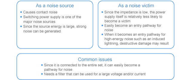
Since power supply is essentially a circuit that provides only direct current or commercial frequency, it should be unlikely to become a cause or pathway of electromagnetic noise. However, in many cases, it actually becomes a cause or pathway of noise. This is considered to be due to reasons as follows:
- (i)even though the voltage seems stable, its electric current may contain a large amount of high-frequency current flowing to operate the electric circuit
- (ii)since the power line is a shared wire in the circuit, noise is circulated and affects the entire circuit
- (iii)since the ground in particular is often shared throughout the equipment and provides a common voltage, it is hard to separate it
- (iv)since it is the energy source for the equipment, the noise energy also becomes large
Typical examples where the power supply causes noise are contact noise and switching power supply.
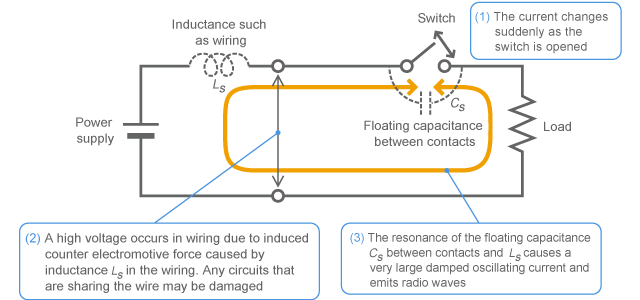
The contact noise is a type of noise that occurs at a point of contact when the source current is turned on/off with a switch (it is particularly strong when turned off), which has the same meaning as the switching surge described in (2) of Section 2-2-3. See Section 2-2-3 for details. Since a very high voltage occurs and the flow of transient but high-frequency current spreads radio waves, it can cause a circuit failure or can lead malfunction of the surrounding electronic devices.
Switching power supply is a circuit that changes voltage and frequency by intermittently flowing the electric current with use of semiconductor. Since the section of intermitting the electric current generates a high-frequency energy, it causes noise interference when it leaks out to the outside. For example, the chopper-type DC-DC converter shown in Fig. 2-2-7 generates the output voltage by intermittently flowing the direct current with use of transistor. This intermittent current contains a high-frequency energy. Although most of this energy is usually absorbed by input capacitors and/or output smoothing circuit, even a small amount of leakage can be a noise source for the surrounding circuits. In order to eliminate noise in the switching power supply, a low-pass filter that uses L and C is used in addition to the input capacitors and/or output smoothing circuit (noise can also be suppressed by improving the performance of input capacitors and output smoothing circuit).
Apart from DC-DC converter, an inverter that drives a motor is also a type of switching power supply that can generate noise.
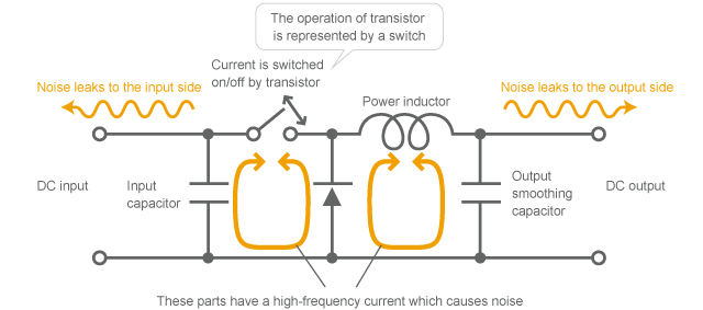
Fig. 2-2-7 Mechanism of causing noise by DC-DC converter
(Simplified model of chopper-type down converter)
In contrast, from the viewpoint of noise victim, power supply is a circuit that is relatively less likely to get affected. Since the amount of energy used internally is large, it will not be easily affected by interference.
However, power supply can be a conduction path for noise. As shown in Fig. 2-2-8, power line is a conductor to directly join electronic devices to each other and is one of the important conduction paths for noise. For example, when an electronic device is affected by noise, or when an electronic device emits noise, the AC power cable becomes a doorway for noise. Therefore, many electronic devices use EMI suppression filters in the power line. Fig. 2-2-9 shows an example of the configuration of EMI suppression filter for AC power supply.
Since the EMI suppression filters used for power supply generally draw an electric current significantly larger than that of signals, parts that are capable of drawing a large current are required.

Fig. 2-2-8 Electronic devices are connected via AC power line
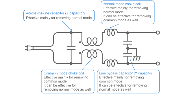
Fig. 2-2-9 Configuration example of EMI suppression filter for AC power supply
2-2-3. Noise occurrence due to surge
An unintended excessive voltage or current due to electrostatic discharge or on-off switching is called surge. Since the level of voltage and/or current is significantly larger than that of normal circuit operation, it can cause malfunction or damage to the circuit. In order to prevent this from happening, surge absorbers are used for the wiring, which surge can enter.
Typical surges are electrostatic surge, switching surge and lightning surge etc. Surge is one of the major categories of EMC measures. It is summarized as follows:
(1) Electrostatic surge
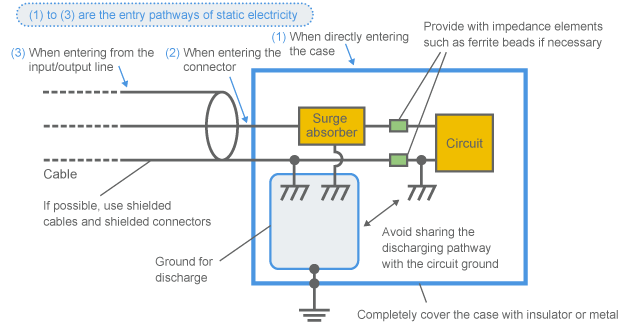
As shown in Fig. 2-2-11, electrostatic surge is a transient noise that happens when an electric charge accumulated in a very small floating electrostatic capacity of about several 100pF sustained in a human body or equipment is discharged to an electronic device or surrounding object. Although its energy is only small, its voltage is as high as several kV or more and a larger current flows instantaneously. Therefore, if it is directly applied to a circuit, it can damage the circuit. Even if it is not directly applied, the circuit may malfunction when the signal line suffers from electromagnetic induction, or when the potential of power supply or ground fluctuates.
One of the tests to simulate electrostatic surge is for example, IEC61000-4-2. Please refer to the test for details.
As shown in Fig. 2-2-12, in order to reduce the interference by static charge,
- (i)cover up with insulator so as to block discharge, or otherwise, cover up with metal so as to divert it.
- (ii)release the discharge current through a pathway that does not affect the circuit (release it to the solid earth to avoid flowing into the signal ground: SG).
- (iii)use an appropriate surge absorber.
Fig. 2-2-11 Entry of electrostatic surge
(2) Switching surge
When the electric current changes suddenly due to relaying or switching on-off (especially when the circuit is turned off), a transient high voltage is induced at the contact point due to the inherent inductance of the circuit. The phenomenon is called switching surge. The contact noise mentioned in Section 2-2-2 is the noise caused by a switching surge.
Since an extremely high voltage occurs, it can show a spark as shown in Figs. 2-2-13 and 2-2-14 or can spread radio waves due to the strong damped oscillating current by the floating electrostatic capacitance at the contact point resonating with inductance. Therefore, it can damage other electronic devices that are sharing a circuit or cause their malfunction. Since this damped oscillating current contains high-frequency components, it can cause reception interference to radios and TVs.
Since resonance that causes a damped oscillating current is an important topic in noise suppression, it will be further described in a different section.
Other than relays and switches, noise generated by DC motor, for example is often caused by the commutator switching the current. Therefore this can be considered as a type of switching surge.
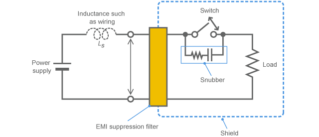
As shown in Fig. 2-2-15, in order to reduce the interference by switching surge,
- (i)use a surge absorber such as a capacitor, varistor and snubber at contact point.
- (ii)provide a shield to shut out any electromagnetic effect.
- (iii)use EMI suppression filters for the noise-transmitting wires and victimized circuits.
In order to achieve some improvement just by shields and filters, it is important to know where the sections that provide the pathway and antenna for noise are. For example, in Fig. 2-2-15, only shielding the switch section does not achieve any improvement at all in most cases (since the wiring outside the shield works as an antenna and emits most of radio waves).

(when the power plug of an oven is pulled out, a spark comes out and a radio makes noise)
(3) Lightning surge
Since lightning is a natural phenomenon and has an extremely large energy, it is very difficult to provide protection against a direct hit. In many cases, instead of providing protection against a direct hit, electronic devices are provided with protection against induced lightning.
Induced lightning is a high voltage induced to a relatively long wiring such as a power line or communication line when a lightning stoke occurs near an electronic device. Possible mechanisms of causing an induced lightning are: electric charge is induced to an electric line due to the electric field caused by thunder cloud and then the electric charge is released by a lightning stoke; or a magnetic field due to the lightning current causes an induced electromotive force in an electric line. Not as hard as direct lightning stroke, but induced lightning has a large energy that is enough to damage electric circuits. So protection is needed.
In order to provide protection against induced lightning, a surge absorber such as a varistor is used at the section where power lines and communication lines go in and out the electronic device.

“2-2. Noise source origin” – Key points
The three points as listed below were described as examples of noise sources and victims. Now we understand that noise suppression can be all different depending on the mechanism of causing noise and what kind of noise you are dealing with. In order to efficiently implement noise suppression, you need to investigate the noise that is causing interference and choose appropriate means in accordance with the cause. Since digital circuit and resonance phenomenon are important topics regarding noise sources, these will be further described in different sections.
- Signal
- Power supply
- Surge

