The EWE Antenna
The EWE antenna developed by Floyd Koontz WA2WVL is something of a little miracle, providing a welcome addition to the armory of any Medium or Short Wave enthusiast.
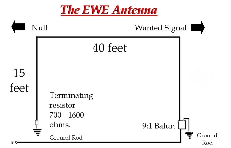
The EWE is a directional low-frequency antenna that can fit in most gardens and provides a null of up to 30 dB off its back.
The one detailed above has the dimensions I use – terminating with an 820-ohm resistor, but a smaller version is commonly in use with listeners measuring 10 by 21 feet and giving more or less the same results. Measurements with this antenna are not entirely critical and the termination resistance has a range between 700 and 1600 ohms dependent on ground conditions. A variable resistor and a steady daytime signal from the rear of the antenna will let you tweak for the best rejection of signals off the back. Resistance needed will also change with frequency so do some experimentation.
Grounding can be achieved with two to three-foot-long copper pipes driven into the earth.
Results can be quite astounding. Living here in Ireland I can null English stations on Medium wave on 1170 and 1530 kHz respectively to produce signals from WWVA West Virginia and AFRTS Iceland.
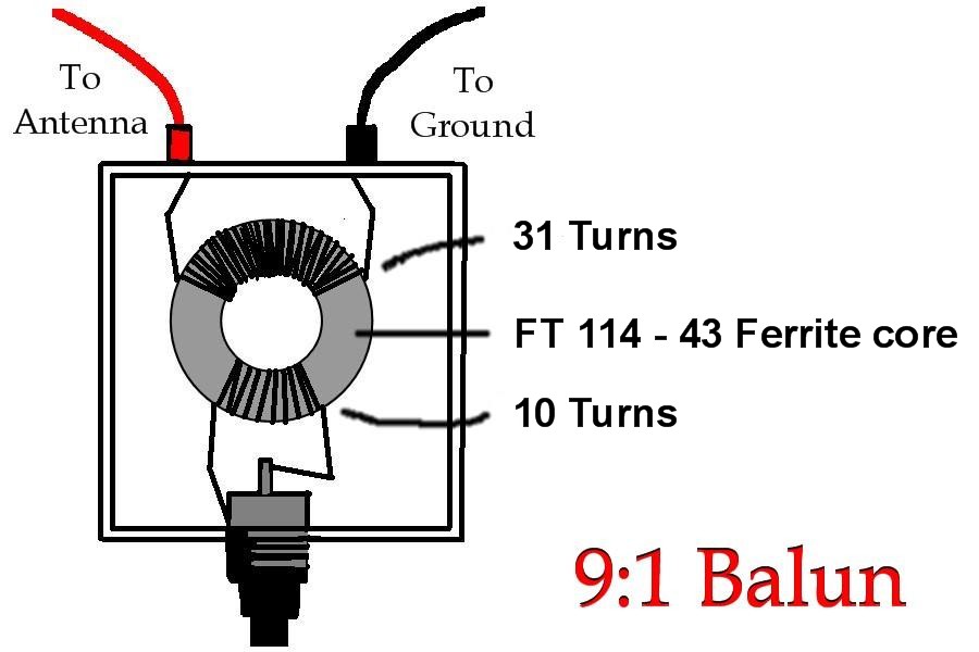
Fabrication of the matching transformer couldn’t be more simple and will allow you to feed this 450-ohm antenna with coax. Two windings are made on a FT 114 – 43 ferrite core good for 500khz to 30 Mhz. This is placed in a weatherproof box with connections of your choosing and you are ready to go!
Alternatively, FT 114 – 75 ferrite cores can be used for slightly better performance on Long Wave – down to 200 kHz the winding ratio here is 13 to 4.
Smaller ferrite cores such as the FT 50 – 75 can also be used – the winding ratio is 27 to 9 and will cover 200khz to 15 MHz.
 Some other optimal lengths for the EWE are:
For 3.8 MHz – 10 x 25 feet – 850-ohm termination
For 1.8 MHz – 10 x 40 feet – 1060-ohm termination.
For combined 160 / 80 meters 15 x 38 feet 840-ohm termination.
You must be logged in to post a comment.