Copper Wire, Toroids, and Transformers

Wire and its Uses
Wire and its Uses
Conductive wire has many uses, this page is mostly
concerned with its uses in electronics, specifically in
amateur radio design and construction.
There is a metric standard for wire measurement,
and of course, it is very simple.
And, as you might expect, the system used in the U.S. is
enormously complicated and non-intuitive.
But if you don’t live in the U.S. with its peculiar wire
gauge system you will still see designs using inductors
and transformers constructed with U.S.-specific wire sizes.
So, we need to look at the specifics of the American Wire Gauge
or AWG system, and some handy rules of thumb for working
with it.
Then, some details about making inductors and transformers
with that wire!
Toroidal inductors have many advantages,
so we’ll look at the toroidal cores commonly used
in ham designs.
American Wire Gauge
The American Wire Gauge or AWG is used in the U.S. and Canada for electrically conducting wire. Steel wire uses various different wire gauges — one for the type of wire you would use to repair a fence or hang a picture, another for that used on musical instruments, and so on.
The electrical current capacity depends on the cross-sectional area and not the diameter. This means that the formulas are more complicated than you might expect for diameter versus wire gauge number or for the relationship between the diameters of two different gauge numbers.
Counter-intuitively, larger gauge numbers mean smaller wire.
Why?
This comes from the production process. The wire is formed by drawing the original copper stock material through a series of increasingly smaller dies. A smaller final diameter requires more passes through the dies. The final gauge number isn’t exactly the number of die passes, but generally speaking, the higher gauge numbers mean larger numbers of die passes and therefore smaller final diameters.
There is a gauge 0, which is large, plus increasingly larger multiple-zero sizes up to 0000 which is also written as 4/0. Power distribution conductors larger than 4/0 are usually identified by their area in thousands of circular mils, but if you’re doing industrial work or designing and building power distribution networks you shouldn’t need this page to tell you how to do that!
The formal notation is the number followed by “AWG” as in 12 AWG However, you will also see #12, Number 12 or No. 12, No. 12 AWG, and 12 gauge or 12 ga.
For the large multi-zero sizes the formal notation is something like 0000 AWG. But you will also see 4/0 (pronounced “four aught”), 4/0 AWG, #0000 AWG, and #4/0.
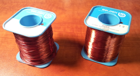
Two spools of enameled copper wire. #24 at left, #34 at right.
AWG Rules of Thumb
We’ll get to the formulas and tables in a moment, but let’s start with some simple rules of thumb. All these are approximate but still useful.
If you double the diameter the AWG decreases by 6. Or, half the diameter means the AWG increases by 6.
If you double the cross-sectional area the AWG decreases by 3. Or, twice the area means the AWG increases by 3.
If you decrease the AWG by ten gauge numbers (e.g., #24 to #14) the area and weight are multiplied by about 10 and the resistance is divided by about 10.
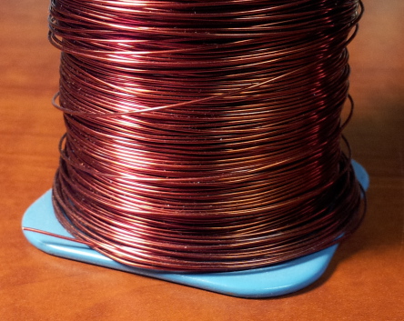
Spool of #24 enameled copper wire.
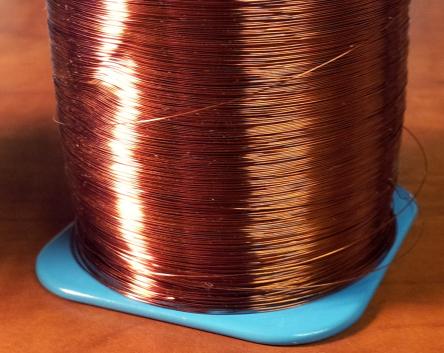
Spool of #34 enameled copper wire.
Aluminum wire has a conductivity of about 60% that of copper, so the aluminum wire has about the same resistance as copper wire 2 gauge sizes smaller.
Stranded wire is also described by AWG, where it also defines the cross-sectional area. Since about 10% of the cross-section of the multi-stranded wire is air, the stranded version will be about 5% thicker than the solid wire of the same AWG. Stranded wire will be described with three numbers indicating the overall AWG of the bundle, the number of strands, and the AWG of the individual strands. 22 AWG 7/30 is the result of using seven strands of 30 AWG wire to create one 22 AWG-stranded wire bundle.
AWG Formulas
The way that AWG works is that #4/0 AWG and #36 AWG are defined by diameter.
#4/0 AWG = 0.46 inches
#36 AWG = 0.005 inches
All the other gauges are defined mathematically. The ratio of those two diameters is 1:92, and the gauges are 39 steps apart. The diameters are then very geometrically. Formally, the ratio of two consecutive gauge diameters is the 39th root of 92, or approximately 1:1.1229322. But the ASTM B 258-02 standard says don’t go overboard on numerical precision! Use no more than 4 significant digits, with no finer than 0.0001 inches or 0.1 mil precision for #44 AWG and larger (which will cover almost everything most of us will ever use), and no finer than 0.00001 or 0.01 mil for smaller wires.
Equations provide a straightforward way of calculating diameters, areas, and gauge numbers. For multi-aught M/0 wire, use N = 1–M in the following equations. For example, for 4/0 use -3 for N.
The diameter of #N AWG wire is:
dN = 0.005 × 92(36-N)/39 inch
dN = 0.127 × 92(36-N)/39 mm
The AWG gauge N of a wire of diameter d inch is:
N = –39 × log92(d/0.005) + 36
The AWG gauge N of a wire of diameter d mm is:
N = –39 × log92(d/0.127) + 36
The cross-sectional area of #N AWG wire is:
AN = 0.000019635 × 92(36-N)/19.5 inch2
AN = 0.012668 × 92(36-N)/19.5 mm2
As with most everything else, the metric version is much simpler. The Metric Gauge is 10 times the diameter in millimeters. However, metric wire sizes are usually specified simply by their diameter in millimeters.
Copper Wire Tables
| AWG | Diameter | Resistance | ||
| inch | mm | ?/1000 ft | ?/1000 m | |
| 0000 | 0.4600 | 11.684 | 0.04901 | 0.1608 |
| 000 | 0.4096 | 10.405 | 0.06180 | 0.2028 |
| 00 | 0.3648 | 9.266 | 0.07793 | 0.2557 |
| 0 | 0.3249 | 8.251 | 0.09827 | 0.3224 |
| 1 | 0.2893 | 7.348 | 0.1239 | 0.4066 |
| 2 | 0.2576 | 6.544 | 0.1563 | 0.5127 |
| 3 | 0.2294 | 5.827 | 0.1970 | 0.6465 |
| 4 | 0.2043 | 5.189 | 0.2485 | 0.8152 |
| 5 | 0.1819 | 4.621 | 0.3133 | 1.028 |
| 6 | 0.1620 | 4.115 | 0.3951 | 1.296 |
| 7 | 0.1433 | 3.665 | 0.4982 | 1.634 |
| 8 | 0.1285 | 3.264 | 0.6282 | 2.061 |
| 9 | 0.1144 | 2.906 | 0.7921 | 2.599 |
| 10 | 0.1019 | 2.588 | 0.9989 | 3.277 |
| 11 | 0.0907 | 2.305 | 1.260 | 4.132 |
| 12 | 0.0808 | 2.053 | 1.588 | 5.211 |
| 13 | 0.0720 | 1.828 | 2.003 | 6.571 |
| 14 | 0.0641 | 1.628 | 2.525 | 8.286 |
| 15 | 0.0571 | 1.450 | 3.184 | 10.45 |
| 16 | 0.0508 | 1.291 | 4.016 | 13.17 |
| 17 | 0.0453 | 1.150 | 5.064 | 16.61 |
| 18 | 0.0403 | 1.024 | 6.385 | 20.95 |
| AWG | Diameter | Resistance | ||
| inch | mm | ?/1000 ft | ?/1000 m | |
| 19 | 0.0359 | 0.912 | 8.051 | 26.42 |
| 20 | 0.0320 | 0.812 | 10.15 | 33.31 |
| 21 | 0.0285 | 0.723 | 12.80 | 42.00 |
| 22 | 0.0253 | 0.644 | 16.14 | 52.96 |
| 23 | 0.0226 | 0.573 | 20.36 | 66.79 |
| 24 | 0.0201 | 0.511 | 25.67 | 84.22 |
| 25 | 0.0179 | 0.455 | 32.37 | 106.2 |
| 26 | 0.0159 | 0.405 | 40.81 | 133.9 |
| 27 | 0.0142 | 0.361 | 51.47 | 168.9 |
| 28 | 0.0126 | 0.321 | 64.90 | 212.9 |
| 29 | 0.0113 | 0.286 | 81.84 | 268.5 |
| 30 | 0.0100 | 0.255 | 103.2 | 338.6 |
| 31 | 0.00893 | 0.227 | 130.1 | 426.9 |
| 32 | 0.00795 | 0.202 | 164.1 | 538.3 |
| 33 | 0.00708 | 0.180 | 206.9 | 678.8 |
| 34 | 0.00630 | 0.160 | 260.9 | 856.0 |
| 35 | 0.00561 | 0.143 | 329.0 | 1079 |
| 36 | 0.00500 | 0.127 | 414.8 | 1361 |
| 37 | 0.00445 | 0.113 | 523.1 | 1716 |
| 38 | 0.00397 | 0.101 | 659.6 | 2164 |
| 39 | 0.00353 | 0.0897 | 831.8 | 2729 |
| 40 | 0.00314 | 0.0799 | 1049 | 3441 |
The U.S. National Electric Code or NEC specifies ampacity or current limits for wires. These are for individual wires and not wires bundled into Romex or other sheathed multi-conductor cables where the allowed current limits are much lower. The limits depend on the insulation’s temperature rating to 60°C, 75°C, and 90°C.
| AWG | Ampacity for insulation |
||
| 60°C | 75°C | 90°C | |
| 0000 | 195 | 230 | 260 |
| 000 | 165 | 200 | 225 |
| 00 | 145 | 175 | 195 |
| 0 | 125 | 150 | 170 |
| 1 | 110 | 130 | 150 |
| 2 | 95 | 115 | 130 |
| 3 | 85 | 100 | 110 |
| 4 | 75 | 85 | 95 |
| 6 | 55 | 65 | 75 |
| 8 | 40 | 50 | 55 |
| 10 | 30 | 35 | 40 |
| 12 | 25 | 25 | 30 |
| 14 | 20 | 20 | 25 |
| 16 | — | — | 18 |
| 14 | — | — | 14 |
Toroidal Inductors
Toroidal inductors are wound with magnet wire on a toroidal core as seen here. This toroid shape is like a donut or bagel, so the resulting inductor is shaped like a simple solenoid or spring-shaped inductor that has been wrapped almost into a complete circle.
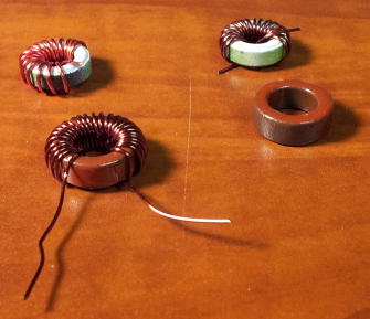
Toroidal Inductors
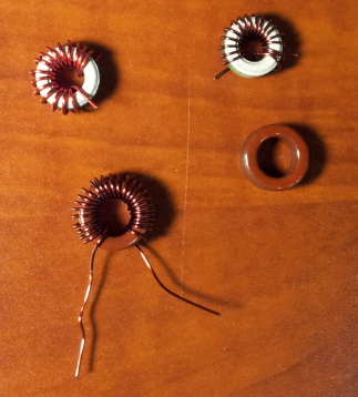
Toroidal Inductors
Toroidal cores have advantages over simple solenoid inductors. To start with, they’re self-shielding. Their magnetic field goes around and stays largely within the core. You can place them close to each other with much less unwanted coupling. You can also place them close to conducting surfaces without worrying about inducing currents in those surfaces and suffering the associated loss.
Also, the toroid cores themselves are made from mixes of iron powder and other chemicals. This material has a much higher permeability than air, so it takes much less looping wire to create the same amount of inductance. The inductors are physically much smaller and they have far less loss than an air-core equivalent.
You form the inductor with magnet wire, which is made from electrolytically refined copper and is coated with a flexible insulating surface. We traditionally call this “enameled wire”. However, modern magnet wire is not coated with any enamel material. It instead is coated with one to four layers of polymer film insulation.
Polyvinyl formal (also called Formvar) is used for applications with the lowest temperature range. Polyurethane, polyamide, and polyester are used for increasing temperatures, and then polyester-polyimide, polyamide-polyimide, and finally polyimide for operation up to 250°C.
The newer magnet wire insulation acts as a flux when it is heated by molten solder, meaning that we don’t have to scrape or sand the ends. But the old stuff we get in surplus needs mechanical cleaning to get a good solder joint.
You want the turns to occupy about 5/6 to 9/10 of the circumference of the core, evenly spaced.
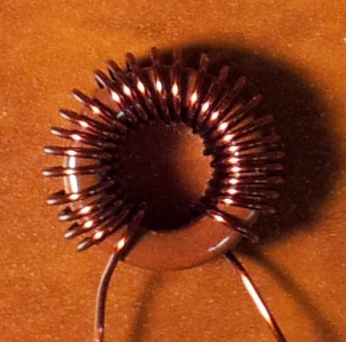
For optimal Q or quality factor, you would like for the wire to be as large as possible while still fitting all the turns with no overlap around the inner circumference. The insulated turns around the inside may all touch each other or at least come very close.
You can see that on the toroidal inductor seen here. You count one turn for each pass through the center. It has 27 turns. It may be easier to count the full loops around the exterior and then add one.
Toroidal Cores
There are two major classes of toroidal core material: ferrite and powdered iron.
Ferrite toroids are used to fabricate larger inductances used to filter out or block higher frequency signals. They are lossy at higher frequencies and that’s exactly what you want. The cylindrical bulge near each end of a computer video cable is a barrel-shaped ferrite core that the entire bundle passes through. It blocks “common-mode” signals, high-frequency signals that would be radiated by the cable if they flowed basically in unison on the bundle.
Powdered iron toroids are used to fabricate fairly precise inductances to be used in filters or other tuned circuits up to 100 MHz.
Ferrite toroids are designated FT-ss-t and powdered iron toroids as T-ss-t where ss is a two- or three-digit number indicating outer diameter in hundreds of an inch, and t is a one- or two-digit number indicating the material mix.
A T-50 toroid is 0.50″ in outer diameter, a T-130 is 1.30″ in outer diameter, and so on. They range from a tiny T-12 (which actually is 0.125″ across) up to the 2″ T-200.
The material mix specifies the core’s permeability, stability, and appropriate frequency range. Micrometals manufacture most of the powdered iron toroidal cores used by amateurs, and they paint the cores to indicate the material.
As you see from this table, some of the mix numbers increase with both frequency range and permeability or ?, but many do not.
Stability is in parts-per-million per degree C.
| Micrometals Toroidal Cores | |||||
| Mix | Color | Freq (MHz) | Stability | ? | Material |
| 3 | grey | 0.05–0.5 | 370 | 35 | Carbonyl HP |
| 15 | red/white | 0.1–2 | 190 | 25 | Carbonyl GS6 |
| 1 | blue | 0.5–5 | 280 | 20 | Carbonyl C |
| 2 | red | 2–30 | 95 | 10 | Carbonyl E |
| 7 | white | 3–35 | 30 | 9 | Carbonyl TH |
| 6 | yellow | 10–50 | 35 | 8 | Carbonyl SF |
| 10 | black | 30–100 | 150 | 6 | Powdered iron W |
| 17 | blue/yellow | 40–180 | 50 | 4 | Carbonyl |
| 12 | green/white | 50–200 | 170 | 4 | Synthetic oxide |
Alinco and other vendors use a handy inductance index AL which is ?H per 100 turns for powdered iron cores.
Use the below table to find AL for the core size and material, and then apply these formulas to calculate the required number of turns N for the desired inductance in ?H or the resulting inductance in ?H for a given number of turns N:
N = 100 × sqrt ( L?H / AL )
L?H = AL × N2 / 10000
| AL Values for Micrometals Iron Powder Toroidal Cores | |||||||||
| Size | Mix/Color / Frequency (MHz) | ||||||||
| 3 / grey 0.05–0.5 |
15 / red/wht 0.1–2 |
1 / blue 0.5–5 |
2 / red 2–30 |
7 / white 3–35 |
6 / yellow 10–50 |
10 / black 30–100 |
17 / blu/yel 40–180 |
12 / grn/wht 50–200 |
|
| T-12 | 60 | 50 | 48 | 20 | 18 | 17 | 12 | 7.5 | 7.5 |
| T-16 | 61 | 55 | 44 | 22 | — | 19 | 13 | 8 | 8 |
| T-20 | 76 | 65 | 52 | 27 | 24 | 22 | 16 | 10 | 10 |
| T-25 | 100 | 85 | 70 | 34 | 29 | 27 | 19 | 12 | 12 |
| T-30 | 140 | 93 | 85 | 43 | 37 | 36 | 25 | 16 | 16 |
| T-37 | 120 | 90 | 80 | 40 | 32 | 30 | 25 | 15 | 15 |
| T-44 | 180 | 160 | 105 | 52 | 46 | 42 | 33 | 18.5 | 18.5 |
| T-50 | 175 | 135 | 100 | 49 | 43 | 40 | 31 | 18 | 18 |
| T-68 | 195 | 180 | 115 | 57 | 52 | 47 | 32 | 21 | 21 |
| T-80 | 180 | 170 | 115 | 55 | 50 | 45 | 32 | 22 | 22 |
| T-94 | 248 | 200 | 160 | 84 | — | 70 | 58 | 32 | — |
| T-106 | 450 | 345 | 325 | 135 | 133 | 116 | — | — | — |
| T-130 | 350 | 250 | 200 | 110 | 103 | 96 | — | — | — |
| T-157 | 420 | 360 | 320 | 140 | — | 115 | — | — | — |
| T-184 | 720 | — | 500 | 240 | — | 195 | — | — | — |
| T-200 | 425 | — | 250 | 120 | 105 | 100 | — | — | — |
Now you have selected a core size and mix, and calculated how many turns of wire are required, you can use the first table below to estimate the largest size of wire that can make that many single-layer turns. Estimate it as it will depend on coating thickness and precisely how you wind the coil.
You can find tables for even finer wire, but even this table goes beyond the limit of practicality for most applications.
These should cover almost all the inductances you would ever need for practical circuits for resonant circuits or for bandpass and high- and low-pass filters when used in combination with practical capacitor values through the HF and into the low VHF range.
| Maximum Turns | ||||||||||
| AWG | T-12 | T-25 | T-37 | T-50 | T-68 | T-80 | T-94 | T-106 | T-130 | T-200 |
| 12 | – | – | 3 | 6 | 9 | 14 | 16 | 16 | 25 | 43 |
| 14 | – | 1 | 5 | 8 | 13 | 18 | 21 | 21 | 32 | 54 |
| 16 | – | 2 | 7 | 13 | 17 | 24 | 28 | 28 | 41 | 69 |
| 18 | 1 | 4 | 10 | 18 | 23 | 32 | 37 | 37 | 53 | 88 |
| 20 | 1 | 6 | 14 | 23 | 29 | 41 | 47 | 47 | 67 | 111 |
| 22 | 2 | 9 | 19 | 30 | 38 | 53 | 60 | 60 | 86 | 140 |
| 24 | 4 | 13 | 25 | 39 | 49 | 67 | 77 | 77 | 109 | 177 |
| 26 | 7 | 17 | 33 | 50 | 63 | 85 | 97 | 97 | 137 | 223 |
| 28 | 9 | 23 | 42 | 64 | 80 | 108 | 123 | 123 | 173 | 281 |
| 30 | 13 | 29 | 54 | 81 | 101 | 136 | 154 | 154 | 217 | 355 |
| 32 | 17 | 38 | 68 | 103 | 127 | 171 | 194 | 194 | 272 | 439 |
| 34 | 23 | 49 | 88 | 132 | 162 | 218 | 247 | 247 | 346 | 557 |
| AL Values for Ferrite Toroidal Cores in mH/1000 turns | |||||
| Core | 63/67 mix ? = 40 |
61 mix ? = 125 |
43 mix ? = 850 |
77/72 mix ? = 2000 |
J/75 mix ? = 5000 |
| FT-23 | 7.9 | 24.8 | 188 | 396 | 980 |
| FT-37 | 19.7 | 55.3 | 420 | 884 | 2196 |
| FT-50 | 22.0 | 68.0 | 523 | 1100 | 2715 |
| FT-82 | 22.4 | 73.3 | 557 | 1170 | — |
| FT-114 | 25.4 | 79.3 | 603 | 1270 | 3170 |
For the last of the toroid tables, here are the AL values for ferrite toroids. Note that AL is in mH per 1000 turns for ferrite toroids!
Apply these formulas to calculate the required number of turns N for the desired inductance in mH or the resulting inductance in mH for a given number of turns N:
N = 1000 × sqrt ( LmH / AL )
LmH = AL × N2 / 1000000
Ferrite toroids are not color-coded, so it’s hard to tell what an unlabeled one really is. You could quickly wind a simple coil, count the turns and measure its inductance, and then solve for AL to see which of these mixes was used. You often use ferrite cores in situations where you aren’t concerned with the precise value anyway. Slipping ferrite beads onto power supply lines, or slipping the larger barrel-shaped ones salvaged from old computer video cables onto the outside of coaxial feedlines to block common-mode currents at an HF dipole feed.
Power Transformers
Typical power transformers use these wiring color codes. Be careful!
Primary:
If not tapped, two black leads.
If tapped, black and black/red striped with a black/yellow tap.
High voltage:
If not tapped, two red leads. Center-tap would be red/yellow striped.
Rectifier filament winding:
If not tapped, two yellow leads. Center-tap would be yellow/blue striped.
Filament winding #1:
If not tapped, two green leads. Center-tap would be green/yellow striped.
Filament winding #2:
If not tapped, two brown leads. Center-tap would be brown/yellow striped.
Filament winding #3:
If not tapped, two grey leads. Center-tap would be grey/yellow striped.

You must be logged in to post a comment.