| |

T Aerials With Matching Network
Electrical Notes
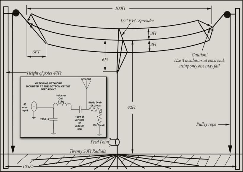
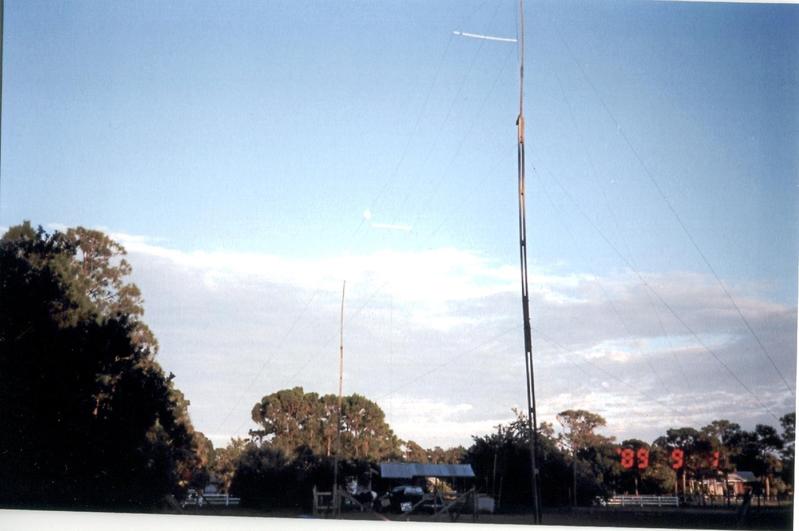
This T aerial broadcast design by Guglielmo Marconi has been built and is used by Jim NN4AA on 160m, all details and drawings are copied from Jim’s Notes he sent me.
As-Built, The aerial will Resonate at 1640khz
This raises the radiation resistance by about 1 ohm over what would result from a resonant configuration.
If the aerial is built higher or longer, a still lower resonate freq will result.
Radiation Res. is 11.5 ohms current in the down lead is about 2.3 amps at 100 watts
Ground resistance is about 6-7 ohms.
Tuning notes
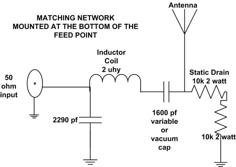
- Put the matching network at the bottom of the aerial where the ground radials terminate.
- The aerial is fed at Jim’s QTH via 400 feet of underground 1/2-inch hardline.
- Since the aerial resonates well below the band, it was tuned up to 1860khz by means of a 1600pf fixed capacitor in series with the down lead.
- Resonance can be determined by connecting the tuning cap directly to the ground via a short clip lead. A grid dip meter can then be coupled to the clip lead. A 2 turn loop may be needed here to get adequate coupling
- Matching L design is then designed to match 50 ohms to 18 ohms for perfect VSWR at 1860khz. 1.5:1 BW is 45khz, 2:1 is 90khz.
- You do not have to duplicate the aerial dimensions exactly, with a shorter flat top resonance could be achieved at your operating frequency. in that instance, the series capacitor would not be needed, but you would still need the L network.

– |


You must be logged in to post a comment.