
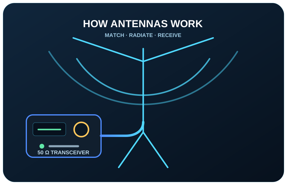
How Antennas Work
From transmitter matching and electromagnetic fields to radiation, reception and dipole resonance.
1. The antenna system must be matched
Modern amateur-radio transmitters are normally designed to work into a 50-ohm load. The impedance presented by an antenna system can be only a few ohms, close to 50 ohms, or several thousand ohms depending on the antenna type, its length, height, surroundings, feed point and operating frequency.
Common ways of achieving a suitable match include:
- adjusting or pruning the antenna to resonance;
- using an antenna tuning unit at the transmitter or feed point;
- using a matching section made from transmission line;
- using a transformer, balun, unun, gamma match, hairpin match or another feed-point network.
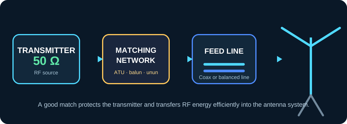
A centre-fed half-wave dipole is one of the simplest practical antennas. In free space its feed-point resistance is about 73 ohms, but at real installation heights and over real ground it is often within a range that a 50-ohm transmitter and feed line can use successfully. The exact impedance is affected by height, nearby objects, ground conditions and the way the feed line is routed.
2. Electric current produces magnetic and electric fields
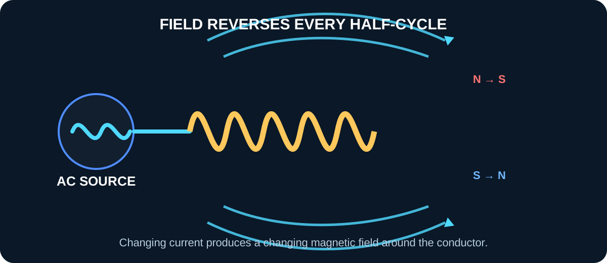
To understand antennas, it helps to understand electromagnetism. When direct current flows through a coil, a magnetic field forms around it and the coil behaves as an electromagnet. When the current is removed, the stored magnetic field collapses.
With alternating current, the current direction and polarity repeatedly reverse. The magnetic field therefore grows, collapses and reverses in step with the applied frequency. Around any conductor carrying radio-frequency current there is also an electric field associated with voltage. Close to the antenna these fields store and return energy; farther away they combine into a travelling electromagnetic wave.
3. A changing magnetic field can induce voltage
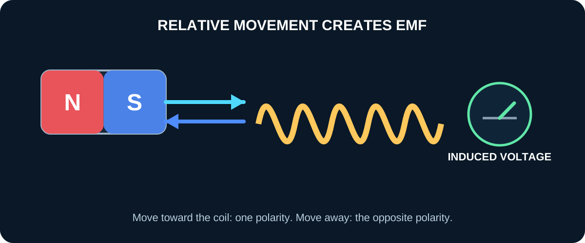
The reverse process is also true. A changing magnetic field passing through a conductor can produce an electromotive force and, if the circuit is complete, a current. This is Faraday's law of electromagnetic induction.
Moving a permanent magnet towards a coil produces a voltage of one polarity. Moving it away reverses the polarity. Repeated back-and-forth movement therefore produces alternating voltage. An electrical generator uses the same principle by rotating a conductor in a magnetic field, or by rotating the magnetic field around the conductor.
4. Mutual induction and transformers
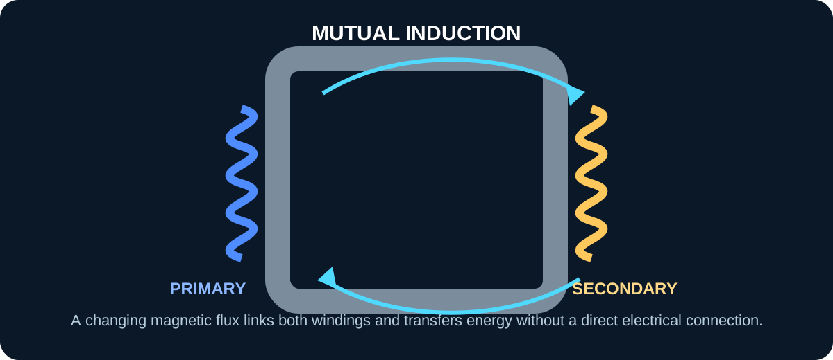
If alternating current flows in one coil, its changing magnetic field can pass through a nearby second coil and induce an alternating voltage in it. This is called mutual induction.
A transformer makes this coupling efficient by using a magnetic core that guides most of the flux through both windings. Antenna transformers, baluns and ununs use related principles, although at radio frequencies their construction, core material, winding arrangement and transmission-line behaviour are critical.
5. How a wire radiates a radio wave
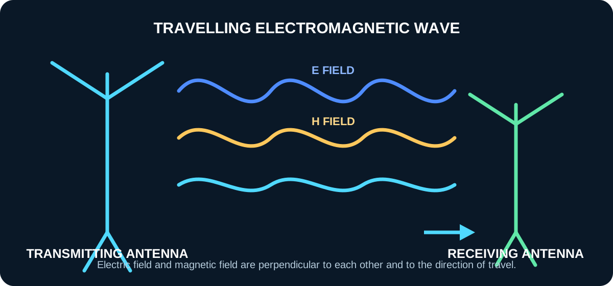
A straight conductor carrying radio-frequency current has changing electric and magnetic fields around it. If the conductor has the correct physical arrangement and current distribution, part of the field energy detaches from the immediate region of the conductor and propagates outward as an electromagnetic wave.
The electric field and magnetic field are at right angles to one another and to the direction of travel. In the far field, the wave no longer depends on the antenna for support and continues through space, weakening as it spreads over a larger area.
6. The receiving antenna
When the travelling electromagnetic field reaches another conductor, it creates a small alternating voltage and current in that conductor. The receiving antenna delivers this weak signal to the receiver input.
The received voltage may be only microvolts, or even less, yet modern receivers can amplify and process it. Reception is strongest when the antenna is suitable for the frequency, has compatible polarisation, is positioned favourably and is connected to a low-loss feed system.
7. Current, voltage and resonance in a dipole
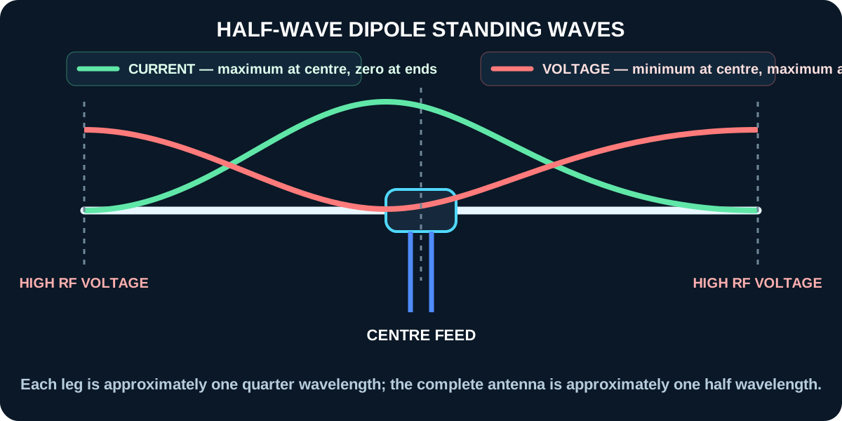
A dipole consists of two conductive legs fed at the centre. During one half-cycle, charge and current move along the two legs in opposite directions. During the next half-cycle the direction reverses.
At resonance, the antenna length and operating frequency support a standing-wave pattern. On a half-wave dipole, current is greatest near the centre and falls towards zero at the ends. Voltage is lowest near the centre and greatest near the ends. This is why the centre is a convenient low-impedance feed point and why the ends can carry high RF voltage.
8. Frequency determines resonant length
Electromagnetic energy travels close to the speed of light, but the effective velocity along an antenna conductor is reduced by the conductor's diameter, insulation, end effects and surroundings. This is why a practical resonant half-wave dipole is normally shorter than one half of a free-space wavelength.
A useful starting formula is:
Each leg is approximately half of that result.
This formula is a starting point, not a guaranteed final length. Install the antenna in its intended position, measure it with an antenna analyser, and trim both legs equally in small steps until resonance is where required.
9. The complete process
- The transmitter produces alternating RF voltage and current.
- The matching system presents a suitable load to the transmitter.
- RF current flows along the feed line and into the antenna.
- Changing current and voltage create changing magnetic and electric fields.
- Part of that energy propagates away as an electromagnetic wave.
- A distant antenna intercepts a tiny part of the field and develops a signal voltage.
- The receiver amplifies, filters and demodulates the signal.
Half-wave dipole starting length
Enter the centre frequency. The result is a practical starting length before final analyser adjustment.